Dimmers
Here's how I control the lights in my apartment:
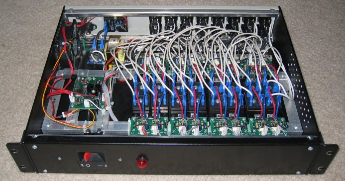
This is a 16-channel computer controlled incandescent light dimmer. It uses reverse phase control with IGBTs, and the turn-off time is controlled so the lights don't "sing" at low levels. It can handle 1200W per channel or 1200W total steady state. I underestimated the inrush current for incandescent lights so only two upgraded channels can handle large loads, but the other channels can be upgraded easily (IGBT replacement) if I need the capacity.
There are two channels per board and two boards per heatsink. Each channel uses one IGBT and rectifier and has its own shunt regulator to provide 15V to the IGBT driver (a TLP351).
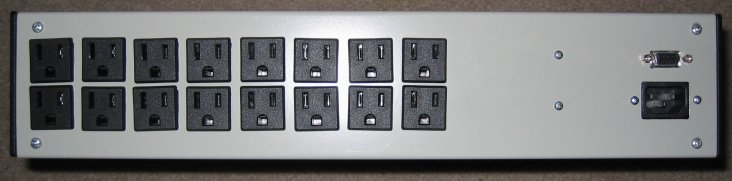
It's built in a stock 2U rackmount case. I made the rectangular cutouts for the outlets and the ventilation holes on a manual mill, and it didn't take as long as I expected.
The computer sends light levels to the dimmer via a serial port. An ATmega16 in the dimmer generates PWM waveforms for 16 channels in software. This takes a lot of time, and my first version (running at 3.6864MHz) required that there not be any loops inside the main loop as there wasn't enough time. I switched to a 14.7456MHz clock and was able to add some features like double-buffering (to prevent levels from changing in the middle of a 60Hz cycle).
The design was inspired by ST's application note on dimming with IGBT's.

Close-up of control and channel boards
History
I had built a four-channel phase control dimmer and some cheesy DC dimmers before, and I had written several versions of control software for it. The old phase control dimmer had several problems:
- Only four channels
- An inconvenient case
- Used triacs for phase control, so lights "sang" at low levels
- I etched the control board myself and some traces were too thin and the weight of components would occasionally break them off the board
- Shock hazard
- Probably a fire hazard
Old dimmer
Host-side
One of my goals was to allow several different programs to control my lights. To do this, I wrote a light server which sits between the dimmers and various client programs. It is the only program which sends data to the dimmers. Lighting data from the clients is represented as "layers". Each client can control multiple layers and can determine how its layer is combined with others. The details are available in the specification, which I wrote partly as an exercise in writing a detailed spec. I wrote the light server in Ada. I wrote both C and Ada client libraries.
Clients communicate with the light server via TCP and UDP. Currently, I routinely run two clients:
- Ambient lighting control
- An XMMS plugin the controls lights based on music.
The dimming hardware and the light server are complete and were operational for several months. I have recently moved and haven't set up the dimmers in the new place.
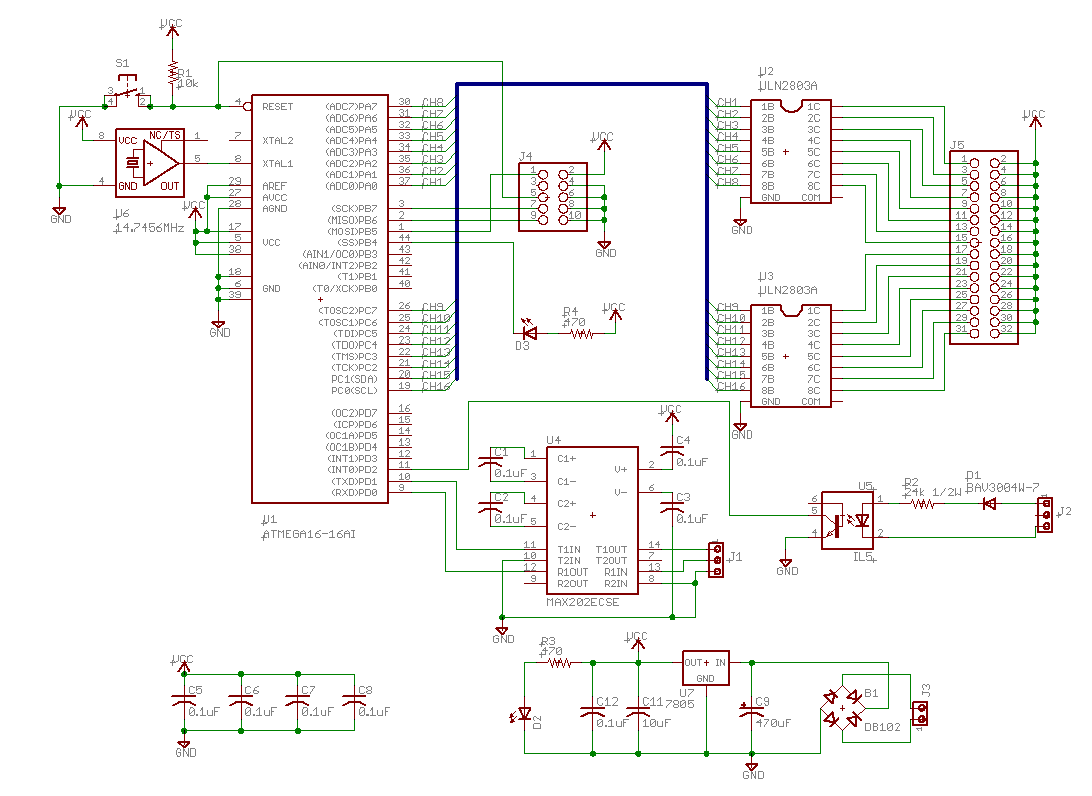
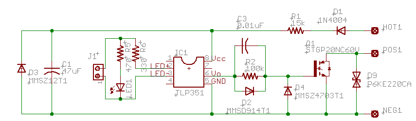
Schematics
I've updated these schematic to show the designs as they are now. I added C3 to the high-voltage boards after they were made to control turn-off time. D9 was added to protect against voltage spikes when bulbs burn out.
Note that R1 on the high-voltage board is a 1/2W resistor.
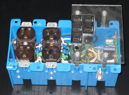
How the high-voltage board is connected
The POS and NEG terminals connect to the positive and negative terminals of a bridge rectifier. HOT connects to the hot line (120VAC). The AC terminals of the rectifier are connected between line neutral and the neutral side of each output socket. This is essentially the same connection as in the ST application note mentioned above except that the shunt regulator is powered directly from hot instead of through the load.
Lessons Learned
- Do thermal design early, and test it.
This includes choosing fans. I went through three fans before I found one that was reliable, quiet, and powerful enough to work. I'm not really happy with the placement of the fan either. - Determine what the inrush current for the load will be and plan for it.
A cold 60W light bulb can draw nearly 10A if it is turned on at the peak of the cycle (neglecting inductance). While this normally doesn't happen with reverse phase control, turning the power to the dimmers on or changing light levels in the middle of a cycle can cause it. I fixed that by double-buffering the lighting levels so that the new levels take effect at the beginning of the next period. - This solid state relay can't be powered off my serial port.
I tried this to reduce power consumption by completely turning off the dimmers when not in use, but my serial port provided only enough current to marginally turn on the relay. When it warmed up, the characteristics of either the relay or the voltage regulator I was using to convert 10V from the serial port to 5V changed enough that the relay would start to turn off and all the lights flickered. - I should have used a switching regulator for the control circuitry.
The 7805 gets pretty hot having to drive 34 LEDs (one status LED and one optoisolator per channel, one power LED, and one MCU status LED). - All those LEDs also put a strain on the original transformer, causing the fan to slow down when the optoisolator LEDs were on more (which means the loads are heavier, which is really the worst time for the fan to slow down). I got a bigger transformer which can provide over 12V all the time and put a voltage regulator on the fan.