RoboJackets TE Board
These boards were designed for the RoboJackets Technical Enrichment sessions of Fall 2005. These sessions are presented annually by Georgia Tech students and alumni to groups of students from Georgia high schools to teach concepts and techniques related to robotics. For more information on these sessions, see the GT FIRST section of the RoboJackets web site.
Features
- Atmel ATmega8 microcontroller
- Two 5A motor drivers (Infineon TLE5206-2)
- Serial port for communications and program loading
- Six general purpose I/O connections
- Joystick connector with three additional inputs
I will provide support for these boards only for Robojackets members and those who got one at the TE sessions. Anyone may use these designs for educational purposes, but I can't commit to providing support beyond what I post on this page.
Programming
To program the boards, you need to get AVR-GCC. If you are running Linux, this is probably provided as a package for your distribution. If you use Windows, you can get an installer here. I suggest you use one of the example programs below as a template and replace the code.
Programs to transfer code can be downloaded here:
If you find a bug in either of these, please report it to me.
There may be a problem with transferring more than 6k of data. There is no legitimate reason to do this, since only 6k bytes are available for user code (the bootloader takes the top 2k).
Examples
Motor test - This example uses a potentiometer to control motor speed. Demonstrates use of the ADC and motor drivers.
State machine - A simple state machine using the buttons for inputs and the LEDs for outputs. Demonstrates use of the buttons and LEDs.
Each of these examples contains a Makefile for building the code and some code to initialize the board and provide easy access to buttons, LEDs, and the motor drivers. To build the code, all you need to do is:
in the directory where the code is stored. This creates a .bin file which is used by one of the downloader programs (above) to program the board.
The file rjte.h contains definitions of functions, variables, and macros that are helpful in using the buttons, LEDs, and motors.
You really need to get the datasheet for the ATmega8 from Atmel's web site to understand how to use the microcontroller. There are also lots of examples online for this series of microcontrollers.
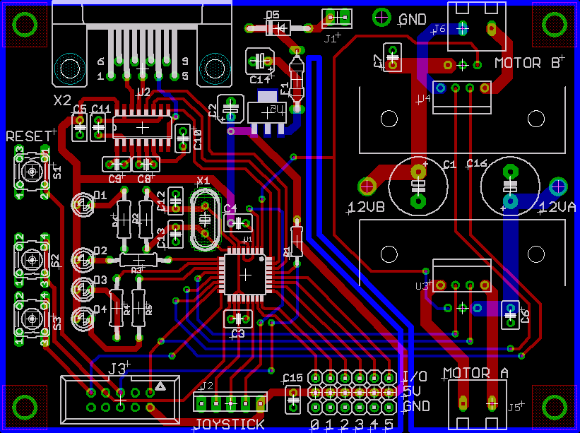
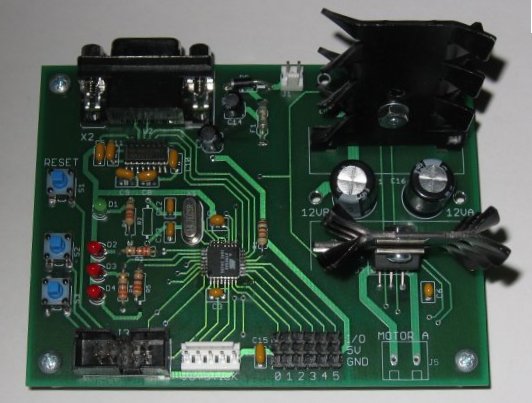
Hardware
These boards were designed with the free version of Eagle and fabricated by PCB Express (this is different from ExpressPCB). The boards were assembled and tested by Robojackets members.
The Eagle files for the boards can be downloaded here. This design can be edited using the free version of Eagle.
The schematic and PCB layout are available as images so you don't have to use Eagle to view them.
Port pin assignments
Port B:
| Pin | Dir | Description |
|---|---|---|
| PB0 | Out | Motor A direction |
| PB1 | Out | Motor A speed (OC1A) |
| PB2 | Out | Motor B speed (OC1B) |
| PB3 | Out | Motor B direction |
| PB4 | In | Button 2 (SW3) |
| PB5 | In | Button 1 (SW2) |
Port C:
| Pin | Description |
|---|---|
| PC0 | I/O 0 |
| PC1 | I/O 1 |
| PC2 | I/O 2 |
| PC3 | I/O 3 |
| PC4 | I/O 4 |
| PC5 | I/O 5 |
| PC6 | /RESET (Not usable as I/O) |
| ADC6 | Joystick X |
| ADC7 | Joystick Y |
PC0-PC5 may be set to input or output depending on their use. They are not connected to anything on the board except the I/O headers.
ADC6 and ADC7 are analog inputs only and are not general purpose I/O pins.
PC6 is the reset line for the microcontroller and cannot be used for I/O. Its direction and output bits are ignored.
Port D:
| Pin | Dir | Description |
|---|---|---|
| PD0 | In | Serial RXD |
| PD1 | Out | Serial TXD |
| PD2 | In | Serial DTR (PROG) |
| PD3 | In | Motor error flag (INT1) |
| PD4 | In | Joystick button |
| PD5 | Out | LED 1 (D2), active low |
| PD6 | Out | LED 2 (D3), active low |
| PD7 | Out | LED 3 (D4), active low |
Motor Driver Error Behavior
The motor driver error flag (PD3) is driven low by either motor driver when an error condition occurs (typically overcurrent). This is an open-collector output so the pull-up resistor on the microcontroller must be turned out (by setting the output bit for PD3 to 1).
When a motor driver error occurs, the error flag goes low and stays low until either input to the motor driver changes. If the motor speed is not zero or full, this will happen quickly because of the PWM speed signal. Until the error flag is cleared, the motor driver with the error will disconnect its outputs from both supplies, allowing the motor to spin freely.
Bootloader
If you want to write your own downloader (or fix a bug in mine), you should read the serial protocol.
The bootloader should be already loaded on any board you want to use. I suspect that some boards were built but the boot loader was not installed (I found one), so if the downloader program doesn't do anything after you reset the board, then that's probably the problem.. The easy way to fix this is to ask me to do it. To load the bootloader yourself, you need to get the bootloader code from the link below, build it, and program the board with an ISP cable:
make prog_config
make prog
The prog_config target erases the microcontroller and sets the fuse bytes. This is necessary for the boot loader to run at reset.
The prog target erases the microcontroller and loads the bootloader code.
The Makefile uses uisp for programming. The ISPFLAGS variable is used to pass programmer-specific parameters to uisp. Currently it is set for an STK500. Note that if you use an STK500, you need to disconnect the Vtarget jumper (since the RJTE board provides power) and set Vtarget to 0.1V.
The bootloader runs in the boot block at reset. The boot block is set to be the top 1024 words, leaving 3k words (6k bytes) for user code. User code is built normally, as if it were run at startup from address 0. If the bootloader does not detect a request to download code, it will run the user code from the normal reset vector (address 0). This allows user code to be run without the bootloader without modification.
The bootloader source can be downloaded here.
Notes
Since Motor B direction is connected to MOSI, it would be a good idea not to use the ISP programming connector while a motor is connected.
There are no known electrical errors on the boards. There are two mechanical errors, one of which is insignificant:
- The site for resistor R1 (pull-up for /RESET) is sized for a 1/8W resistor, while 1/4W was intended and ordered.
- The two motor connectors (J5 and J6) have holes that are too small for the pins on the connectors.
Most boards were assembled with a 1/4W resistor for R1 mounted slightly off the board. This error has no effect on the performance of the board.
The holes for the motor connectors can't be drilled out to fit since there are traces on the top of the board which can't be soldered with the connector in place, and drilling removes the plating in the holes. Our fix was to solder wires to the board and run these to an off-board terminal block. This worked out fine since the layout of the plastic sheet made the terminal block more convenient anyway.
R2 should not be populated. It was added in case of problems with the crystal oscillator, but was determined not to be necessary.