Sirius Front Panel
Introduction
I recently got a used Sirius satellite radio receiver. It didn't have an antenna (or presumably a subscription), and I don't listen to radio much, so I was more interested in the hardware as parts than as a radio. The front panel looks useful, especially when you take the thing apart and find out that the front panel has an ATmega128 controlling it!
On further investigation, it seems that the radio and front panel operate mostly independently, with only a serial link and a few discrete signals connecting them. There is information on the web about connecting the radio to a computer via this serial link, but that's not what I'm after. The front panel has 17 rubber buttons, an encoder with a button, an IR detector, and a monochrome LCD screen with a red backlight. There are test points on the board for programming the ATmega128 at the factory. See where I'm going with this?
The board is only two layers, and the only large chip is the ATmega128, so almost everything was easy to figure out. The one problem was the LCD screen. It has no useful part numbers (this happens a lot), and no exposed chips. The controller/driver is a bare die mounted on the flex cable, as in many cell phones.
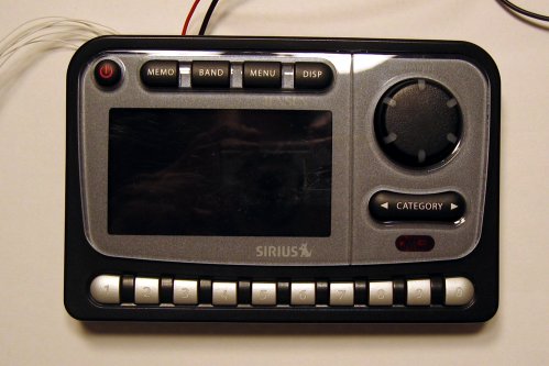
Front Panel
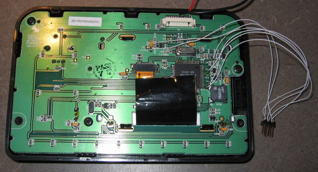
Back, with wires for ISP and power
The silkscreen text in the upper left corner reads:
Satellite Radio
SIR-PNP2.REV.1
(CK100SR.REV.0)
2004.03.25
MCU pinout
This was determined by following traces on the board. See below for how the LCD signals were identified.
| Pin | Description |
|---|---|
| PA0 | Button column 1 |
| PA1 | Button column 2 |
| PA2 | Button column 3 |
| PA3 | Button column 4 |
| PA4 | Button column 5 |
| PA5 | Button column 6 |
| PA6 | Encoder 1 |
| PA7 | Encoder 2 |
| PB0 | |
| PB1 | ISP SCK |
| PB2 | |
| PB3 | |
| PB4 | FM_CNT (OC0) |
| PB5 | Beeper (OC1A) |
| PB6 | LCD backlight control (OC1B) |
| PB7 | P_EN (power enable to radio) (OC2/OC1C) |
| PC0 | LCD D0 |
| PC1 | LCD D1 |
| PC2 | LCD D2 |
| PC3 | LCD D3 |
| PC4 | LCD D4 |
| PC5 | LCD D5 |
| PC6 | LCD D6 |
| PC7 | LCD D7 |
| PD0 | Button backlight control |
| PD1 | |
| PD2 | RX (from radio) |
| PD3 | TX (to radio) |
| PD4 | LCD /RD |
| PD5 | LCD /WR |
| PD6 | LCD RS |
| PD7 | LCD /RESET |
| PE0 | ISP MOSI |
| PE1 | ISP MISO |
| PE2 | |
| PE3 | |
| PE4 | |
| PE5 | |
| PE6 | IR detector |
| PE7 | |
| PF0 | |
| PF1 | |
| PF2 | |
| PF3 | |
| PF4 | |
| PF5 | Button row C |
| PF6 | Button row A |
| PF7 | Button row B |
I haven't messed with the thing beside the IR detector which is either an IR emitter or a light level sensor.
LCD
Since I couldn't get any information from the screen itself, I captured the initialization sequence, one bit at a time, with an oscilloscope (I have since bought a logic analyzer) and made some educated guesses about what the signals did. It was pretty clear that the LCD had to have its own controller, since the ATmega128 shouldn't be loaded down with constantly refreshing the screen, so the interface was probably similar to other graphic LCDs with a built-in controller. All of port C was probably eight data lines, since that was eight adjacent data lines. One signal (PD7) has an RC filter on it and pulses only on startup, so it was probably a reset. The remaining three signals had to contain a read/write line (or seperate read and write lines) and one or two register select lines.
The activity on the three control lines suggested that there were seperate read and write signals, since all three showed lots of activity on startup (when the logo was being drawn) but in different patterns. I started reading all the datasheets I could find for graphic LCD controllers that might be used for this display and found that the Samsung S6B1713 has an interface that is consistent with my observations. Most importantly, the bytes I captured from the data lines made sense as initialization commands for this chip.
The lock bits were set on the MCU, so after recording some other timing details I erased the chip and started working on my own code. I imitated the initialization sequence that I recorded and eventually got the LCD to initialize and display data. Later I wrote text display code using a free 8x8 bitmap font.
It turns out that the screen is 132x65, the largest size supported by the S6B1713.
Buttons
The buttons are wired in a 3x6 matrix. I labelled the columns 1-6 and the rows A-C. This table shows which keys are in which positions in the matrix:
| 1 | 2 | 3 | 4 | 5 | 6 | |
|---|---|---|---|---|---|---|
| A | 1 | 2 | 3 | 4 | 5 | 6 |
| B | 7 | 8 | 9 | 0 | Cat. Right | Cat. Left |
| C | Power | MEMO | BAND | MENU | DISP | Encoder |
Code
You can get my code and misuse your own radio's front panel, or use it as example code for other purposes. The font code is probably useful if you have an S6B1713, but the code depends on that chip's addressing scheme so it may not be helpful for other LCD screens.
The encoder code is not the best and doesn't debounce, so you really shouldn't reuse it. This code is really just proof-of-concept.